
Technical Notes
1930's Schematic Notation
Capacitors
Most of the diagrams on this site use notation that is almost identical to that used in modern circuit diagrams today. However, some manufacturers used in-house notations or archaic notations that are no longer used today.
Perhaps most obvious, and easiest to deal with, is the notation for capacitor values. While today we might represent a 0.1 microfarad capacitor as 0.1µF, in the 30's and 40's it was very common to substitute the mu (µ) with a lowercase m, for "micro". So a 0.1µF capacitor would be a 0.1mF capacitor in an old diagram.
A little harder to get used to is the notation for smaller value capacitors. Back then, they didn't use the prefix "pico-" to mean a trillionth of something, instead they prefixed "micro-" with another "micro-". In other words, a 120 pF capacitor would be represented as 120 mmF - 120 micro-microfarad.
Resistors
The differences between modern and old representations for capacitors are minor compared to those for resistors.
For starters, the omega symbol (Ω) is often not used to represent ohms. Instead, many diagrams will either spell out "ohm" or use a lower case omega (ω). So a 10 kilohm resistor might be represented as 10kω.
But a diagram using the archaic ω might not use K to mean a thousand. Instead, it might use the really archaic M (or lower case m). So 10mω or 10Mω mean the same thing as the modern 10kΩ.
Example:
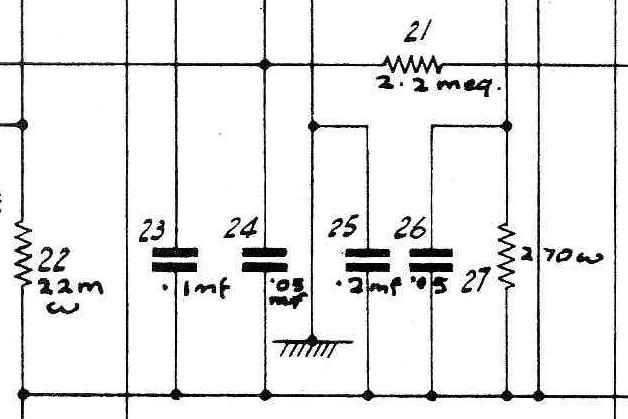 Fig.1. Part 22 is 22kilohms, part 21 is 2.2 megohms, and part 27 is 270 ohms.
It gets better! A few of the diagrams on this site which use "M" to represent 1000, use the capital omega (Ω) to represent one million! So a 1 megohm resistor would be represented as 1Ω !!! You can imagine the disaster that might be caused by replacing that 1 meg resistor with a 1 ohm resistor, no thanks to this "feature!" Thankfully there are very few like this.
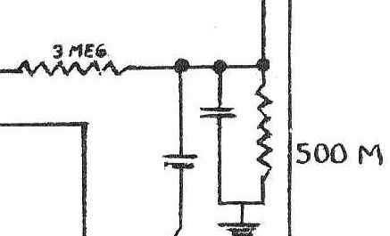 Fig. 2: Another example of the use of "M" for 1000. Pictured are a 3 megohm and a 500kilohm resistor.
Tubes
Most diagrams do not indicate the pin numbers of the tubes - it was assumed by the manufacturers, and by us for that matter, that anyone needing to service radios with their diagrams would already have access to the necessary tube basing information. You should have a tube cross-reference and basing diagram reference before you start. Of course, with careful circuit tracing (aka reverse engineering) you could gain that information on your own.
Readability
We have done our very best to preserve the quality of the diagrams as best we could, with the material we had to work with. We have three sets of the RCC sheets, and all three showed the same problems in the same places, leading us to believe that the printing process for the original sheets left something to be desired. Indeed, they didn't have 2450dpi digital linotypes back in the 1940s. The "originals" were printed inexpensively and quickly with quality no better than that of a mimeograph machine. This led to some unfortunate artifacts that we were able to compensate for in some cases, and which we had to leave as-is in others.
Addison - faint diagrams
We had to do extensive manual cleanup and enhancements on many of the Addison diagrams. The problem is that the originals we worked with were printed very faintly on one side. With digital contrast enhancement and manual cleanup of spots and yellowing we were able to mostly clean up the Addison sheets but they are still by no means perfect. If we ever come across another source, for example a service manual from Addison itself, we will consider re-scanning those pages.
Westinghouse - black tubes
Many of the Westinghouse diagrams have the tube internals drawn in white on a black background. This inevitably led to ink bleed which rendered many of the details of the tube internals unreadable. Why Westinghouse chose to draw their diagrams this way is beyond us, and we were unable to find an enhancement method that would improve this.
Example:
|
|
To read these, note that the plate is visible in even the worst example. It is always on the right. So the elements of the tube are, from left to right, heater - cathode - grid(s) - plate. A tube basing diagram of the tube you are trying to read will help resolve any confusion. Alternatively you could look through other, more readable Westinghouse diagrams on this site for the same tube type to see its elements. With a tube basing manual, you could also work out where each tube subcomponent goes.
White space and Sheet numbers
We found it necessary to trim away "white space" at the edges of the sheets after scanning, in order to make proper print formatting easier. We found that a lot of white space, especially at the top and left edge, resulted in diagrams that were cut off at the bottom and right edge, when printed. In the process, we found it necessary to modify the sheet numbers in some diagrams. In most, we left the sheet numbers exactly where they were, while in others we cut and pasted them to a different place on the page, in still others we typed the sheet numbers in elsewhere on the page, and in a few we just cut the sheet number off completely. All of these modifications enabled us to remove more white space and improve the printability of these diagrams. In any case, the page number of every sheet is part of its file name, so it is really not necessary to have sheet numbers on the sheets themselves.